For measurement of a significant temperature change or temperature measurement in a short temperature cycle period, the response of the temperature measuring sensor is the most important.
For temperature measurement with thermocouples, heat dissipation from the thermocouple tip and the contact area have a great impact on the responsivity.
Comparison of Responsivity by Difference in Tip Shape
Typical thermocouple with a spherical tip
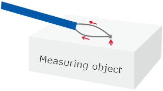
Due to the point contact of the measuring object with the sensing part, the heat input amount is small.
Also, the element wire diameter is not small, which causes more heat to escape and response to be slower.
Ultra-fine thermocouple
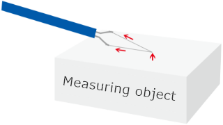
With a small tip diameter, the thermocouple gains heat quickly.
In addition, as less heat escapes to the element wire, a rapid response is achieved.
Ultra-thin thermocouple
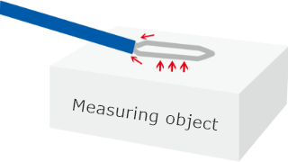
The end of the thermocouple is sheet type and thin, creating a large contact area with the measuring object and leading to rapid heat gain.
Furthermore, less heat escapes compared to a heat input quantity, leading to a faster response.
Comparative Experiment of Thermocouple Characteristics 1: Response Under Adiabatic Compression
We created a fire syringe for testing and performed an experiment.
Place ANBE SMT’s ultra-fine thermocouple (Red: 13 μm, Blue: 25 μm, Green:50 μm)and
a conventional thermocouple (Purple: 200μm, with a spherical tip) inside the device and measure the temperature under adiabatic compression.
The graph shows the smaller the tip diameter is, the better the response is.
The fast-response thermocouple measures temperature without missing instantaneous temperature change.
Comparative Experiment of Thermocouple Characteristics 2: Temperature Measurement Inside Engine
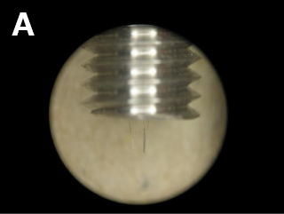
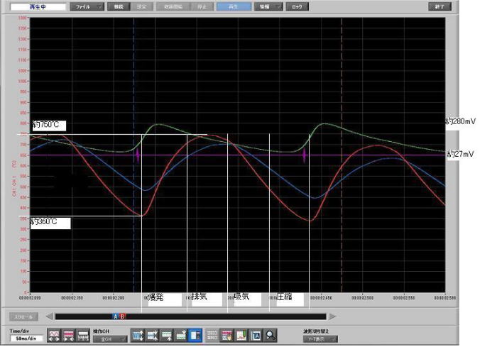
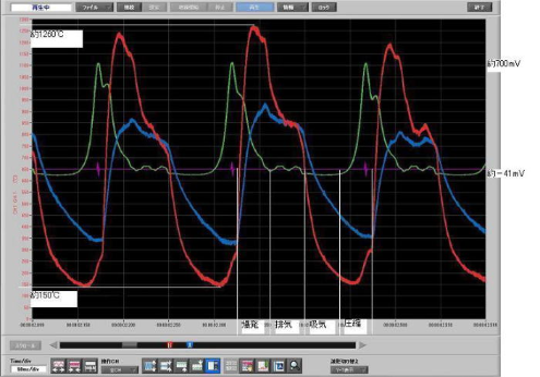
Insert the custom-made thermocouple-A (two wire type of 25 μm and 50 μm in diameter) into the engine and measure the temperature and pressure inside the 4-cycle engine.
This 4-cycle engine performs the following in one process:
- Intake for 50 msec
- Compression for 50 msec
- Combustion for 50 msec
- Exhaust for 50 msec
The operations above are repeated.
A scale of the horizontal axis: 50 msec
Red line: Indicates the temperature at the tip of 25 μm in diameter (unit indicated on the left)
Blue line: Indicates the temperature at the tip of 50 μm in diameter (unit indicated on the left)
Green line: Indicates pressure in mV (unit indicated on the right).
600 rotations (as 4 cycles in one rotation) /minute
800 rotations (as 4 cycles in one rotation) /minute
The following results were obtained by measuring the temperature inside the engine with ANBE SMT’s thermocouple.
| Max. Temp. (Tip 25 μ) |
Min. Temp. (Tip 25 μ) |
ΔT25μ | Max. Temp. (Tip 50 μ) |
Min. Temp. (50μ) |
ΔT50μ | Time required for 4 cycles | ΔP (Pressure) |
|
|---|---|---|---|---|---|---|---|---|
| 600rpm | 750℃ | 360℃ | 390℃ | 720℃ | 480℃ | 240℃ | 200msec | 253mV |
| 800rpm | 1260℃ | 150℃ | 1110℃ | 940℃ | 320℃ | 620℃ | 150msec | 741mV |
It is clear that the thermometer with tip diameter of 25 μ measures the temperature difference in one temperature cycle more accurately.
From the above, the thermocouple can measure the temperature close to the true temperature inside the engine.
Thus, it can be imagined that increasing the engine’s rpm achieves higher energy efficiency than increasing the engine’s displacement.
Comparative Experiment of Thermocouple Characteristics 3: Measurement of Temperature Inside Starring Engine
Embed the ultra-fine thermocouple with the tip diameter of 25 μm into the cylinder of the starring engine to obtain a temperature profile.
 Starring engine sold mainly as a teaching material. Burn a candle on the bottom of the cylinder on the left, and the cylinder rotates rapidly. The 25 μm ultra-fine thermocouple is inserted into the cylinder. The following indicates the experiment results:
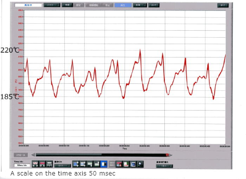
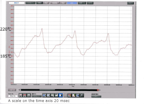
Several small waveforms can be observed in one cycle. This shows that the ultra-fine thermocouple senses a delicate temperature change.
From these results, it can be assumed that the thermocouple still can response faster.
